|
|
3次元の問題における境界条件の指定方法は2次元におけるアプローチを拡張したものです。
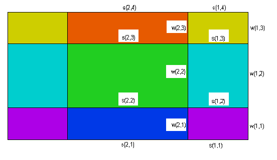
次の図では別個に境界条件が設定し得る種々の表面に対しラベルを付してあります。レイヤ間の境界面に対しては "s" というラベルを、側面に対しては壁という意味合いで "w" というラベルを用いています。この図では断面図に現れる側面しか示してありませんが、実際には基盤平面上の境界線を表す個々の線分/円弧が別個の側面を形成し得るわけで、それらすべてに対し "w" タイプの境界条件を設定できます。
これらの境界面/側面に対する境界条件をすべて設定するとすれば次のような構成となります。
BOUNDARIES SURFACE 1 s(all, 1) { boundary conditions on surface 1 over full domain } SURFACE 2 s(all, 2) { boundary conditions on surface 2 over full domain } {…other surfaces } REGION 1 SURFACE 1 s(1,1) { boundary conditions on surface 1, restricted to region 1 } SURFACE 2 s(1,2) { boundary conditions on surface 2, restricted to region 1 } … START(,) { -- begin the perimeter of region m } w(1,..) { boundary conditions on following segments of sidewall of region 1 on all layers } LAYER 1 w(1,1) { boundary conditions on following segments of sidewall of region 1, restricted to layer 1 } LAYER 2 w(1,2) { boundary conditions on following segments of sidewall of region 1, restricted to layer 2 } … LINE TO .... { segments of the base plane boundary with above BC's } LAYER 1 w(1,1) { new boundary conditions on following segments of sidewall of region 1, restricted to layer 1 } … LINE TO .... { continue the perimeter of region 1 with modified boundary conditions } TO CLOSE REGION 2 SURFACE 1 s(2,1) { boundary conditions on surface 1, restricted to region 2 } SURFACE 2 s(2,2) { boundary conditions on surface 2, restricted to region 2 } … START(,) { -- begin the perimeter of region m } w(2,..) { boundary conditions on following segments of sidewall of region 2 on all layers } LAYER 1 w(2,1) { boundary conditions on following segments of sidewall of region 2, restricted to layer 1 } LAYER 2 w(2,2) { boundary conditions on following segments of sidewall of region 2, restricted to layer 2 } … LINE TO .... { segments of the base plane boundary with above BC's }
LAYER 1 w(2,1) { new boundary conditions on following segments of sidewall of region 2, restricted to layer 1 } … LINE TO .... { continue the perimeter of region 2 with modified boundary conditions } TO CLOSE
2次元の場合と同様、スクリプト中で後に現れるREGIONは前に出てきたリージョンの一部、もしくはすべてを上書きすることになります。例えば基盤平面上のREGION 1の広がりは、その外周によって規定されるもののうちで他のREGIONには含まれない部分となります。
例えば今、キャニスターの表面に一定の温度 "Tcan" を設定したいとしましょう。ドメイン中のキャニスター部は3つの表面、すなわち底面、上面、側面から構成されます。
キャニスターの底面、上面を規定するレイヤ境界の表面には 'Can Bottom', 'Can Top' という名称を付けてあります。今温度を設定したい領域はこれらの表面の中でREGION 2の上部に位置する部分だけなので、REGION 2の定義内においてSURFACEという修飾詞を付けて境界条件を設定します。
一方、キャニスターの側面はREGION 2の境界線をextrudeしたもののうち、'Can' というレイヤに含まれる部分です。従ってここではLAYERという修飾詞を付けてREGION 2の境界線に対する境界条件を設定します。
BOUNDARIESセクション上での設定は次のようになります。
BOUNDARIES REGION 1 'box' START(-1,-1) VALUE(Phi)=0 LINE TO (1,-1) NATURAL(Phi)=0 LINE TO (1,1) VALUE(Phi)=1 LINE TO (-1,1) NATURAL(Phi)=0 LINE TO CLOSE REGION 2 'blob' { the embedded blob } SURFACE 'Can Bottom' VALUE(Phi)=Tcan SURFACE 'Can Top' VALUE(Phi)=Tcan { parameter redefinition in the 'Can' layer only: } LAYER 2 k = 0.001 START 'ring' (R,0) { boundary condition in the 'Can' layer only: } LAYER 'Can' VALUE(Phi)=Tcan ARC(CENTER=0,0) ANGLE=360 TO CLOSE
|